Pipeline Manager
 Provides an interface to create,
modify and manage the pipelines in the model.
Provides an interface to create,
modify and manage the pipelines in the model.
Pipeline Grid
The Pipelines grid list all of the Pipelines currently defined in the model as well as the properties defined for each pipeline. The name of the pipeline is listed in the Name column with the additional properties listed in the adjacent columns.
The order of the columns can be rearranged using the drag and drop method. A default set of property columns are displayed, however, additional property columns can be added or removed from the grid using the right-click context menu. (See Sort Columns section below)
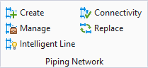
The Pipeline Manager has a series of command icons at the top of the Pipeline grid which provide the following options to create/edit/manipulate the pipelines in the model:
| Pipeline Filter Options | Show All
 - Display active and referenced
pipelines in the grid. (Note that the referenced pipelines will be grayed out
in the grid.) - Display active and referenced
pipelines in the grid. (Note that the referenced pipelines will be grayed out
in the grid.)
Show Referenced
 - Displays the pipelines that are
active in the model. - Displays the pipelines that are
active in the model.
|
| Filter Text Box | Filters pipelines based on all displayed properties. (i.e. - Type in a Service value to display only those pipelines which belong to that service type.) |
Reload Pipeline Manager

|
Reloads the pipeline manager while preserving
the selection of pipelines. Clicking on reload updates newly added/ deleted
components in pipeline manager.
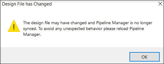
Also whenever a change in the pipeline is detected, it displays the following dialog. Clicking Yes reloads the pipeline manager reflecting the pipeline changes i.e updates the list of newly added components. |
Create Pipeline

|
Displays the Create Pipeline dialog allowing you to create a new pipeline and define properties for the line. From this dialog you are also able to assign project associations to the pipeline. How To |
Delete Pipeline

|
Deletes the selected pipeline. If the pipeline has component assigned to it, a message displays prompting you to either delete the components or move them to another pipeline before you perform the delete option. |
Edit Pipeline

|
Displays a modified version of the Create Pipeline dialog which allows you to edit existing properties and/or define additional properties for the selected pipeline. |
Edit Insulation

|
Displays the Edit Insulation dialog which allows you to edit/define insulation material and insulation thickness for the selected pipeline. How To |
Check Connectivity

|
The Connectivity Checker option checks for proper connectivity along piping runs. Disconnects are displayed in the Connectivity Checker dialog. It should be noted that Modeler checks for connectivity during normal routing activities. Reasons for improper connections are most commonly a result of moving or copying components, then improperly placing them at new locations. How To |
Manage Joint Associations

|
This icon displays the Joint Associations Manager dialog, which list the joint information placed between connecting pipelines in the model. This allows you to view the joint details, including the fasteners and seals, move the joint association from one pipeline to the connecting pipeline if desired. How To |
Export Data for Stress Analysis

|
Displays the OpenPlant Stress Run Interface which creates a PXF file containing the information on the pipelines in the model which can be run through the Bentley AutoPIPE application. |
Generate Spool ID's

|
There are three spool id options available:
|
Isosheet Manager

|
Launches the
IsoSheet Manager allowing you to create/edit IsoSheets from
the selected pipelines.
If no pipelines are selected, the IsoSheet Manager can still be launched and you will be able to select a pipeline from the IsoSheet Manager interface. |
Auto-Generate IsoSheets

|
The Auto-Generate IsoSheets creates
isosheets for a checked pipeline(s) based on connectivity. That is, it looks
for a connected chain of components and creates an isosheet from them. The
connectivity can be broken by adding a isometric breakpoint note on a component
and a new iso-sheet will be created from it.
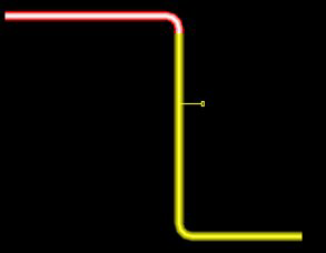
For example, in the model below, an isometric
breakpoint was placed on the vertical pipeline, so the Auto-Generate IsoSheet
generated two iso-sheets (red and yellow) even though they are all connected.
(Limitation)
There is a limitation in the Auto-Generate command in that it looks for an open end and traverses from the first one it finds to the other open end. Depending on the start point, the result can change. For example, in the model below, if you start from top left open end, you will have following two yellow and red isosheets will be created. However, if the start point is the right bottom, then you will have the following output: To avoid the above result, the break point would need to added at the other side of the loop.Note: When
creating Isosheets using the Auto-Generate Isosheets command, any existing
isosheets for the selected pipeline(s) will deleted. The following message
dialog will display warning you of this before you decide to continue:
How To
|
Generate Iso(s)

|
This option (which is also
available from the IsoSheet Manager) generates isometrics from the selected
isosheet(s) and will open the OpenPlant Isometrics Manager providing options to
the user to view the isometric sheets as well as the log files created with the
isometrics.
When accessing this option from the IsoSheet Manager, the user has the option so choose which isosheet(s) to generate isos from if desired. See the IsoSheet Manager for additional info. |
| Isometric Styles | Press the arrow button to select an isometric style from the list: |
 - Displays all pipelines
referenced from the Model Server. (Referenced pipelines cannot be modified.)
- Displays all pipelines
referenced from the Model Server. (Referenced pipelines cannot be modified.)
 : Clears out previous spools if
any, and regenerates the spools.
: Clears out previous spools if
any, and regenerates the spools.
 : Clears out all spools from the
selected pipeline.
: Clears out all spools from the
selected pipeline.


Components Grid
The Components grid expands from the bottom of the Pipeline Manager when you click the Show Component button located at the bottom right of the interface. The grid is hidden by default. This grid lists the components associated with the selected pipeline(s). Components from multiple lines can be displayed simultaneously if desired.
A list of toolbar options are available for the components list. Please refer to the table below for detailed information on the options provided in this toolbar:
| Component Filter | Provides the following options to filter the view in the component grid: |
| Component Selection | Three options are available for quick
multi-component selection: Select All
 : Enables the checkbox next to
all of the components in the list. De-Select All : Enables the checkbox next to
all of the components in the list. De-Select All
 : Disables the checkbox for all
components in the list. Invert Selection : Disables the checkbox for all
components in the list. Invert Selection
 : Will invert whatever the current
selection is. (For Example: If currently all but six components are selected,
this option will enable the six not currently selected, and disable the
remaining components) : Will invert whatever the current
selection is. (For Example: If currently all but six components are selected,
this option will enable the six not currently selected, and disable the
remaining components)
|
Validate Spec Data

|
This option compares the selected component(s) in the DGN to the definitions in the spec database. If a component in the DGN is different than the database, the Spec Validation Dialog displays listing the inconsistencies and allowing you to synchronize the DGN data with the database records. |
Move Components

|
Will move the selected components of one pipeline to another pipeline. Displays the Select Pipeline dialog listing the existing pipelines in the project to choose from. Select the desired pipeline from the list and click OK to move the selected components. How To |
Replace Components

|
Will display the Replace Components dialog allowing you to replace the selected components with a suitable replacement. How To |
Change Spec/Size

|
Displays the Change Spec/Change Size dialog allowing change the size and spec of the selected component(s). How To |
Modify Pipe Bend(s)

|
This option lets you edit multiple pipe
bends from multiple pipelines simultaneously. Select the pipeline(s) from the
Pipeline Grid which have the bends to be modified. Once the components are
listed in the components grid, select the pipe bends from the list and click
the
icon to display the
Edit Pipe Bends dialog. In this dialog, you can modify the
pipe bend properties and apply the changes to all of the selected bends.
|
Assign Spool Ids

|
Displays the Assign Spool Number dialog which lets you define a custom spool id for the selected set of components. |
| View Options | The following options are available: Zoom
 : Zooms into the selected
component : Zooms into the selected
component
Isolate
|
Select

|
Select a component(s) from the grid and click this button to select the components in the drawing for editing or other manipulation commands. |
| Clear View | Clears any highlighting of components previously done using the Highlight and Isolate options. |
 : Hides all other components in
the model except for the selected component. Highlight
: Hides all other components in
the model except for the selected component. Highlight
 : Highlights the selected
component in the model.
: Highlights the selected
component in the model.
Right-click on any of the column headers in either the Pipeline or Component grids and a popup menu displays providing the following options to modify/sort the information displayed in the grid columns:
You now have an option to group components on their component types, through a right click context menu. The menu has the following options to control the display of the data in the Components grid.